Learning ACI - Part 6: Access Policies
16 Jan 2015So far in this series, we’ve covered some basic concepts in ACI, including fabric bringup, APIC familiarisation, application profiles / EPGs / contracts as well as some of the networking concepts in ACI. At some point though, you’ll want to actually start attaching hosts and other devices to the fabric - in order to do this, you’ll need to get familiar with the concept of access policies.
Access policies are used to control parameters relating to access into the fabric, such as which VLANs to use on a port, which leaf nodes and ports should be used for specific hosts or devices, as well as configuration of other access parameters such as LLDP, CDP or storm control.
In this post, I’m going to walk through the creation of an access policy specifically for the connection of a bare metal host to the fabric; I’ll cover VM connectivity in a future post. By the end of this exercise, I will have provisioned a VLAN pool on a particular port on a particular leaf node. One important point is that I am not yet enabling any VLAN on a port - that happens only when I create an EPG and link it to a port. I’ll also say here that there are easier ways of achieving the creation of access policies (using wizards, API, etc). The method I’m using here is somewhat long-winded, but is useful to show the relationship between policies.
So let’s start at the beginning: defining a VLAN pool.
1. Define a VLAN Pool
Although we talk about bridge domains inside the ACI fabric, we still need to use regular VLANs on the link between a leaf node port and the host or device that connects to it. The first thing we need to do as part of our access policy configuration is to define a range of VLANs that are available for this purpose on any given leaf node. From the access policies tab, we’ll expand pools and then VLANs and select Create VLAN Pool. In the example below, I’m creating a new pool with VLANs in the range 500 - 550.
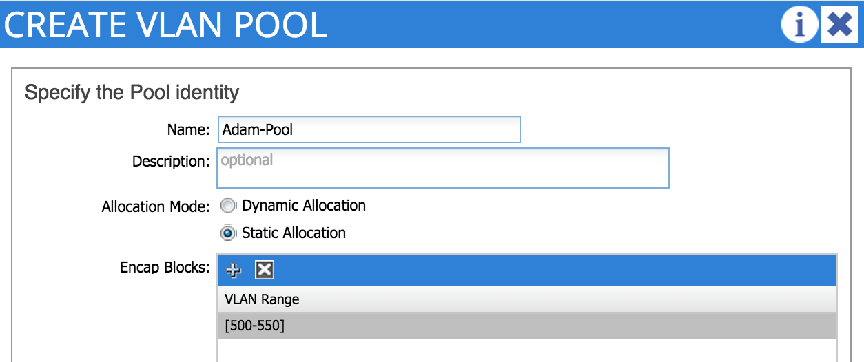
Notice the ‘allocation mode’ option can be set to either ‘static’ or ‘dynamic’. Which one should you choose?
-
Static VLAN allocation mode should be used if the VLAN pool in question will be used for bare metal hosts or other non-virtualised devices. Later, when we create EPGs, we will manually assign a VLAN from the static pool to the EPG and port.
-
Dynamic allocation mode is used when connecting VMs into the fabric , specifically when using VMM integration with the hypervisor management system. In that case, a VLAN will be dynamically assigned to the port group that gets created on the Distributed Virtual Switch. I’ll cover this in more detail in a future post.
In my example, I want to connect a bare metal host, so I choose the static option.
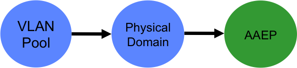
2. Create a Domain
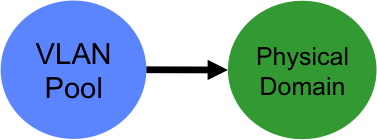
A domain defines the ‘scope’ of a VLAN pool, i.e. where that pool will be applied. A domain could be physical, virtual, or external (either bridged or routed) - in this example I am creating a physical domain as I want to use my VLAN pool for bare metal host connectivity. When you configure a domain, you reference the VLAN pool you created earlier:
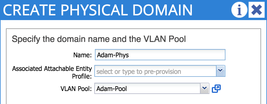
Don’t worry about the Attachable Entity Profile in this step - I’ll cover that next.
3. Create an Attachable Access Entity Profile
Wait…a what?! The AAEP (as I will will refer to it from now on) is a way of grouping together multiple domains that may need to be associated with an interface. In my example, I will refer to my physical domain when creating my AAEP:
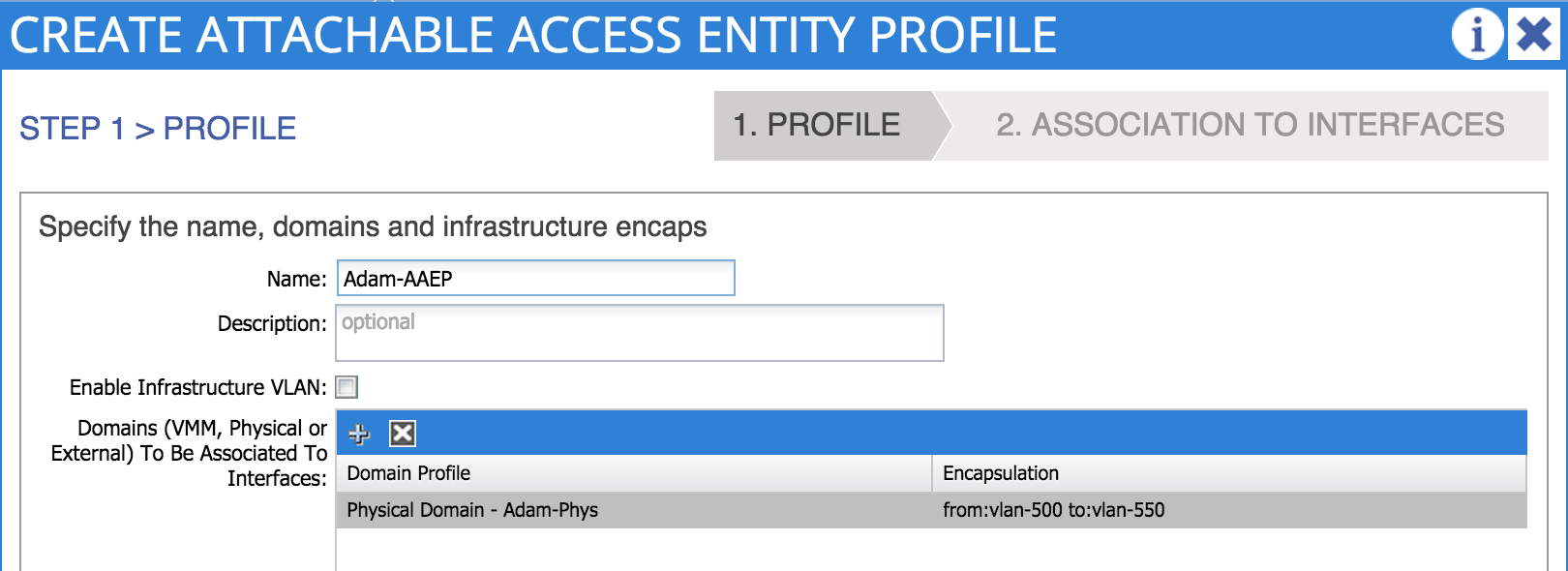
Note that I could attach my AAEP to an interface as part of this step - however, I’m not doing that here so I can explain how that works properly in later steps.
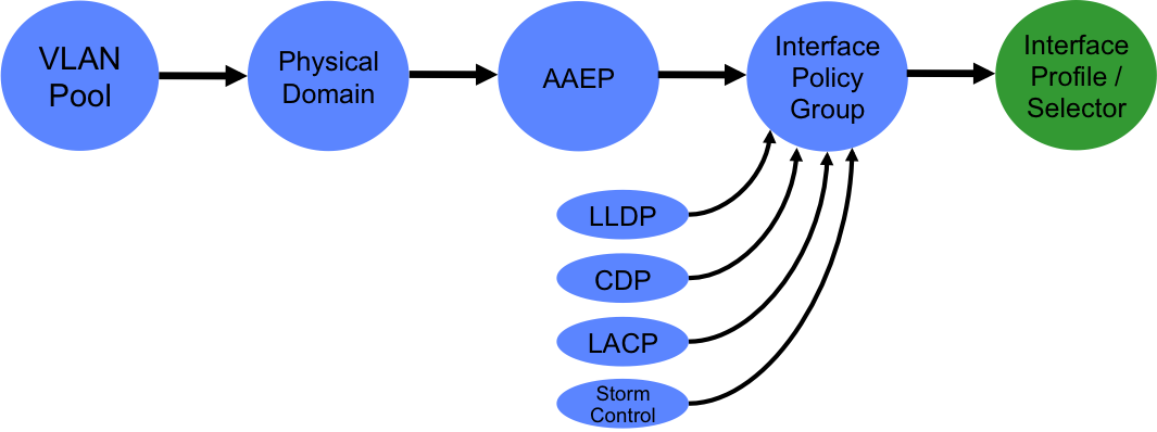
4. Define Interface Policies and an Interface Policy Group
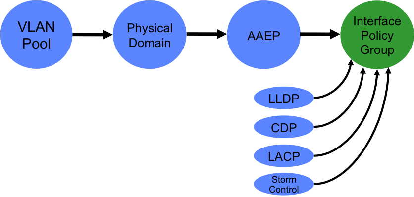
An interface policy is simply a policy which specifies whether a particular feature will be enabled. Examples of features controlled by interface policies are LACP, CDP, LLDP and Storm Control. Interface policies, plus the AAEP we created in the last step are tied together using an interface policy group. You can think of an interface policy group as a port-profile in regular NX-OS environments. In my example, I want to use my AAEP and other policies on a regular access port (not a port-channel or vPC), so specifically I create an access port policy group:
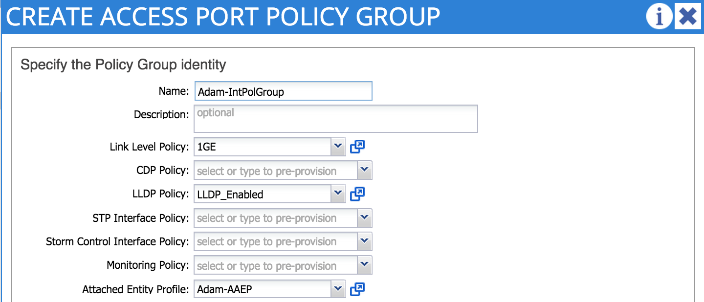
In my example, I am referring to a link level policy that specifies 1Gbps port speed as well as a policy that enables LLDP.
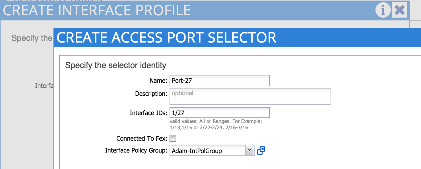
5. Define an Interface Selector and Interface Profile
At this point, we are ready to start applying the policies we have created to one or more interfaces on one or more leaf nodes. The first thing we need to do is to create an interface profile. An interface profile is a policy which contains a port selector. The port selector is used to specify a particular port number - note that we are not yet specifying which leaf node we want to apply the policy to (that happens in the next step). In the example below, I am creating an interface profile containing a port selector referring to port 1/27. Note that the selector policy also refers to the interface policy group I created in the last step.
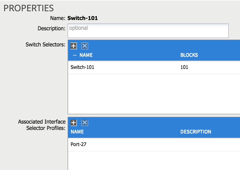
6. Define a Switch Profile
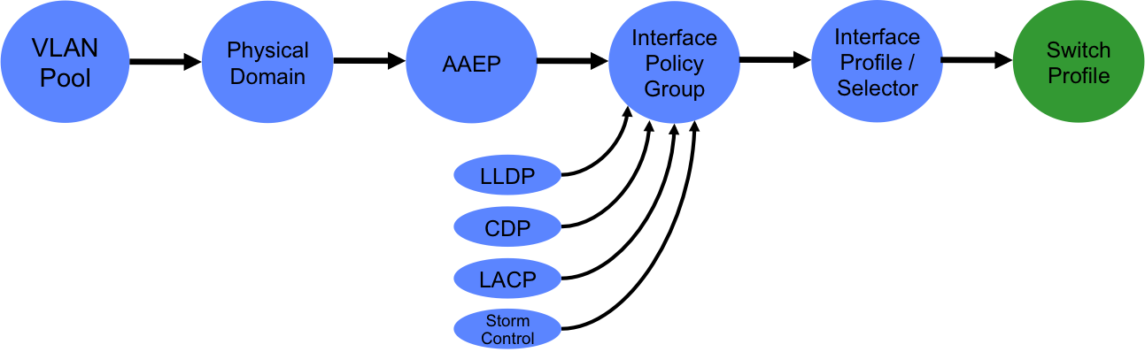
The final step in our access policy journey is to apply the policies we have created to one or more switching nodes (e.g. Nexus 9396 leaves). To do this, we need to define a switch profile. When I create a switch profile I need to refer to two things: the actual switching node I want to apply policy to and the interface profile I defined in the last step. In the example below, I have created a switch profile referring to leaf switch 101 and the ‘port-27’ interface profile I created earlier:
OK, so just to recap - what have we actually achieved by doing this? Fundamentally, we have ‘provisioned’ a range of VLANs on a specific leaf port. At this point, we have not actually enabled any VLANs on the port in question, so no traffic would flow yet (we will need to provision an EPG from the ‘tenants’ tab for that). But the access policy configuration shown above must be done first, before you can provision EPGs. The good news is that this configuration is not something that should be needed on a regular basis - you provision the VLANs and interface policies on the nodes and ports that you need in advance and then simply create EPGs when hosts need to be connected.
Thanks for reading - next time, I’ll look at a simple example of how to get two hosts communicating through the fabric.